


 Home >
 Knowledge Base >
 Community >
 Downloads >
Brake Resistor
General
When servo motors are braked, electrial energy is generated in the motor. This energy is fed back through the brake circuit that is integrated in the servo amplifier p.s.u. to a brake resistor, where it is dissipated as heat. More theoretical explanations are on page Four Quadrant Operation.
Many of our servo amplifier have a built-in brake resistor. However, in some situations the permissible power dissipation of this internal resistor is insufficient. The deciding factors in choosing the right resistor are the resistance value (in ohms) and the required power dissipation. All resistors meet the requirements of CE directives and are UL registered.
Refer to the Accessories Manual for detailed information.
The resistors are available with different power classes, for projecting refer to the page Calculation of brake power.
To avoid any fault during operation the following conditions have to be observed:
- unhindered access of cooling air
- unhindered diverting of warmed up air
- maximum ambient temperature 40°C
Caution: If the ambient temperature is higher than 40°C, you have to lower the continuous dissipation for 4% per 10 K temperature rise!
In cases of insufficient cooling or false mounting the resistor or the surrounding devices could be overheated or damaged.
Current Kollmorgen brake resistors
Overview
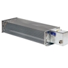
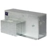
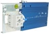
| Type BAFP | Type BAR | Type BAS |
|---|---|---|
 |
|
|
| Flat profile | Tube resistor | Plate resistor |
| IP40 | IP20 | IP20 |
Excess temperature in dependance of continuous dissipation
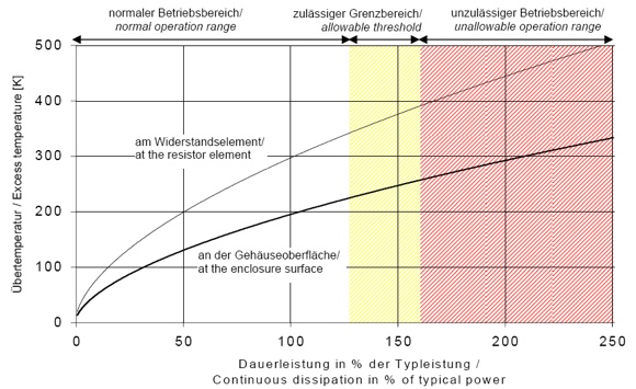
Normal operation range (up to 130%)
Recommended operation range for maximum product life and failure free operation
Allowable threshold (up to 160%)
Allowable operation range, danger of shorter product life and higher failure probability
Unallowable operation range (more than 160%)
Danger of excessive heat and destruction of resistor and neighbouring components
Mounting and distances
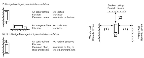
| Free Space | BAFP | BAR | BAS |
|---|---|---|---|
| (1) | 200 mm | 200 mm | 300 mm |
| (2) | 300 mm | 200 mm | 1000 mm |
Documentation and assignment
CE, UL, and RoHS information can be found on page Approvals.
Refer to the Accessories Manual for detailed information.
| Resistance | Rated Power | Max. Power | Max. Operating Voltage | unique nergy absorption every 120 s | Usable for | Drawing | |||||||||
|---|---|---|---|---|---|---|---|---|---|---|---|---|---|---|---|
| Type (data sheet) |
(Ohm) | (W) | (W) | (VDC) | (kWs) | S300 (S3xx61) |
S300 (S3xx01) |
S400 S601...620 S701...712 |
S640 S748 |
S670 S772 |
S724 | AKD- x003...06 |
AKD- |
AKD- x02407 |
3D |
| BAS(U) 2000-10 | 10 | 2000 | 3200 | 850 | 200 | x | STEP | ||||||||
| BAS(U) 3000-10 | 10 | 3000 | 4800 | 850 | 300 | x | STEP | ||||||||
| BAS(U) 6000-10 | 10 | 6000 | 9600 | 850 | 600 | x | STEP | ||||||||
| BAR(U) 500-15 | 15 | 500 | 800 | 850 | 22 | x | x | STEP | |||||||
| BAR(U) 1000-15 | 15 | 1000 | 1600 | 850 | 44 | x | x | STEP | |||||||
| BAS(U) 2000-15 | 15 | 2000 | 3200 | 850 | 200 | x | x | STEP | |||||||
| BAS(U) 3000-15 | 15 | 3000 | 4800 | 850 | 300 | x | x | STEP | |||||||
| BAS(U) 6000-15 | 15 | 6000 | 9600 | 850 | 600 | x | x | STEP | |||||||
| BAR(U) 600-23 | 23 | 600 | 960 | 850 | 30 | x | x | STEP | |||||||
| BAR(U) 1000-23 | 23 | 1000 | 1600 | 850 | 44 | x | x | STEP | |||||||
| BAS(U) 2000-23 | 23 | 2000 | 3200 | 850 | 200 | x | x | STEP | |||||||
| BAS(U) 3000-23 | 23 | 3000 | 4800 | 850 | 300 | x | x | STEP | |||||||
| BAS(U) 4000-23 | 23 | 4000 | 6400 | 850 | 400 | x | x | STEP | |||||||
| BAFP (U) 100-33 | 33 | 100 | 160 | 850 | 2.7 | x | x | STEP | |||||||
| BAFP(U) 200-33 | 33 | 200 | 320 | 850 | 9 | x | x | STEP | |||||||
| BAR(U) 250-33 | 33 | 250 | 400 | 850 | 7 | x | x | STEP | |||||||
| BAR(U) 500-33 | 33 | 500 | 800 | 850 | 30 | x | x | STEP | |||||||
| BAR(U) 1500-33 | 33 | 1500 | 2400 | 850 | 35 | x | x | STEP | |||||||
| BAS(U) 3000-33 | 33 | 3000 | 4800 | 850 | 300 | x | x | STEP | |||||||
| BAR(U) 300-66 | 66 | 300 | 480 | 850 | 7 | x | STEP | ||||||||
| BAR(U) 600-66 | 66 | 600 | 960 | 850 | 22 | x | STEP | ||||||||
| BAR(U) 1000-66 | 66 | 1000 | 1600 | 850 | 44 | x | STEP | ||||||||
| BAR(U) 300-91 | 91 | 300 | 480 | 850 | 7 | x | STEP | ||||||||
| BAR(U) 600-91 | 91 | 600 | 960 | 850 | 22 | x | STEP | ||||||||
| BAR(U) 1000-91 | 91 | 1000 | 1600 | 850 | 44 | x | STEP | ||||||||
