


 Home >
 Knowledge Base >
 Community >
 Downloads >
EnDat
Reference
| Heidenhain Order Code | AKD FB1.SELECT | S300/S700 FBTYPE | S400/S600 FBTYPE | Instruction Set | Incremental Signals |
|---|---|---|---|---|---|
| EnDat 01 | 30, 21 | 4,7,21 | 3,4,6,7,16 | EnDat 2.1 / 2.2 (both possible) |
with |
| EnDat 21 | - | - | - | without | |
| EnDat 02 | 30,21 | 4,7,21 | 6,7,16 | EnDat 2.2 | with |
| EnDat 22 | 31 | 32, 34 | - | EnDat 2.2 | without |
General
The EnDat interface of HEIDENHAIN is a digital, bidirectional interface for gauges. It is able both to distribute position values of incremental and absolute gauges and to select stored information in the gauge, update information or download new information. Due to the serial data transmission 4 signal lines are sufficient. The data are transmitted synchronously to the timing signal provided by subsequent electronics. The selection of the transmission mode (position value, parameters, diagnosis ...) is carried out with mode commands which are sent by subsequent electronics to the guage.

EnDat 2.1
- Absolute position values
- Send and receive parameter
- Reset
- Test command
- Test values
EnDat 2.2 (includes EnDat 2.1)
The extended interface version EnDat 2.2 has compatible communication, command sets and time conditions to the previous version 2.1, offers however clear advantages. It is e.g. possible to transmit additional information with the position value without starting a special query for this. The protocol of the interface was enlarged for this functionality and the time conditions optimized have been as follows:
- Increase clock frequency (CLOCK) 8MHz
- Optimize computing time (position determination in 5µs)
- Minimize recovery time (1.25 to 3.75 µs)
- Position values for increment ale and absolute gauges
- Additional information via the position value
- Diagnosis, test value
- Absolute position values for homing of incremental gauges
- Sending and receiving parameters
- Commutation
- Acceleration
- Limit position signal
Functional description
The EnDat interface transfers position values or additional physical values in unique timely sequence and serves for selecting and describing the gauges of internal memory.
- Position values can be transferred with or without additional information. The additional information itself are selectable by memory area and address. Together with the position value also other functions like parameters read and write can be started after previous selection of the memory area. By the simultaneous transmission with the position value, additional information of the axes situated in the control circuit can be requested and functions can be executed.
- Parameters read and write both as a separate function and in connection with the position value is possible. After the selection of the memory area parameters can be read or written.
- Reset functions serve for resetting the gauge at malfunctions. A reset is possible instead of or during the position value transfer.
- A setup diagnosis already makes a check of the position value possible in the standstill. A test command arranges for the guage to send the corresponding test values.
Data transmission
For the synchronization of the data transmission time a clock is provided by subsequent electronics. The time line is set to high level in the rest condition.
Without run time compensation the clock frequency is variable between 100kHz and 2MHz. The at most permitted clock frequency depends on the cable length between gauge and subsequent electronics (see diagram). Since the signal run time shows high level disturbing level particularly at large cable lengths and higher clock frequencies for the clear assignment of the data, the run time can be checked and compensated by a correction sequence. With this run time compensation in subsequent electronics, clock frequencies up to 8 MHz are possible with a cable length of up to 100m. Special measures have to be taken with a cable length from 30m.
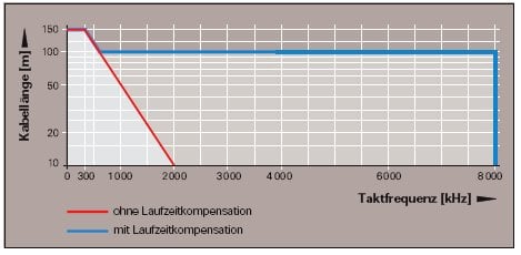
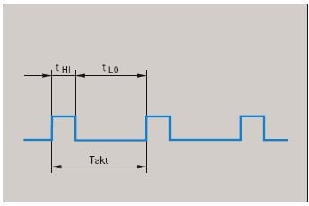
The permitted clock frequencies indicated in the diagrams are valid with a clock duty ratio of 1:1. That means, lengths of high and low levels of the clock are identical. At a divergent clock duty ratio the theoretical clock frequency can be calculated from fc=1/2 tmin.
Determination of the signal run time
After every hardware change of the transmission link the signal run time must be found out, best automatically after every power break.
Subsequent electronics sends the mode command "gauge sends position values to the gauge without additional information" to the gauge. After the gauge has changed to sending, i.e. after 10 clock pulse periods, a counter starts with every rising clock pulse edge in the subsequent electronics. This determines the distance between the last rising clock pulse edge and the flank of the start bit as a signal run time. The process should at least be repeated three times to exclude disturbances during the run time determination and check the value for consistency. The signal run time is determined at reduced clock frequency (100 kHz to 200 kHz). To obtain a sufficient precision, however,you must use an internal frequency that is at least eight times higher than the clock frequency that is used for the data transmission later.

Absolute Encoder with EnDat 2.2

Source
Technische Information Heidenhain GmbH,
02/2004, 383942-12·10·2/2004·F&W

Comments
I would like some further clarification regarding the differentiation between EnDat types, compatibility with Kollmorgen and 3rd party devices, and supported features.
Kollmorgen provides the EQN1125 and EQN1325 encoders on the AKM motors and these have output type of EnDat 2.2/01, which I understand is an EnDat 2.1 equivalent.
Q1: What exactly is EnDat 2.2/01? (Is it EnDat 2.2 hardware with EnDat 2.1 firmware?)
Q2: Does this encoder not support the advanced EnDat 2.2 command set?
Q3: Third party device interfacing: typically if another device is EnDat 2.2 compatible can it operate with an EnDat 2.1 encoder with the limited command set?
Q4: Please confirm: the AKD is not compatible with an EnDat 2.1 encoder without incremental signals (per reference chart above). Additionally does this mean the AKD would not accept an EnDat 2.2/01 encoder if the incremental signals were unwired?
Answer to Question 1: Endat 2.2/01 is the Endat 2.2 version of Endat 2.1. Endat 2.2 is the latest version of Endat, and Heidenhain made an Endat 2.2 version that is the same as Endat 2.1, called Endat 2.2/01. Endat 2.1 and Endat 2.2/01 both consist of analog sine and cosine channels, and the data and clock channels. So in all, there is Sine+, Sine-, Cos+, Cos-, Data+, Data-, Clock+, Clock-.
Answer to Question 2: Endat 2.2/01 and Endat 2.2/22 both have the command set (features) of Endat 2.2.
Answer to Question 3: No. A device compatible with only Endat 2.2 (specifically Endat2.2/22, Data-only) is not compatible with Endat 2.1 or Endat 2.2/01. Endat 2.1 and Endat 2.2/01 use the Sine and Cosine signals for the incremental encoder counts. Endat 2.2/22 is only Data/Clock and uses the data for determining absolute encoder position continuously. In relation to Kollmorgen drives, Endat 2.1 and Endat2.2/01 encoders only use the data channel for determining initial encoder position when the drive boots up. The Endat 2.1 and Endat 2.2/01 data channel is not used after the drive reads the initial encoder position value.
Answer to Question 4: Correct. For use with the AKD, Endat 2.1 and Endat 2.2/01 encoders must use the Sine and Cosine analog signals as the incremental position count. When selecting the AKD feedback mode for Endat 2.1 equivalent (also Endat 2.2/01), the AKD firmware expects to see the analog signals.