


 Home >
 Knowledge Base >
 Community >
 Downloads >
Operating Induction Machines with S400-S600
Valid for S400, S600 with FW 582...5.99, 7.xx
General
We recommend to use the tool Create_Parameterfile_for_Induction_Motor.xls for basic parameterizing. In most cases a good result can be reached with this tool.
Should the result be not sufficient, you must set the parameters described below.
Motor
- Use the tool Create_Parameterfile_for_Induction_Motor.xls for basic parameterizing
- Pole number: check value. Especially with mains frequence deviating from 50Hz a wrong input of pole numbers can occur.
- Magnetising current: this value will be 20% to 60% of the standstill current Io. Principle: the higher this value, the higher is the torque and the lower is the speed limit. Sometimes fine tuning in steps of 0.1 A is necessary. The value must be increased until the motor is able to follow the desired acceleration profile.
- Rotor time constant. with high mass inertia the value that has been generated with the tool must be increased. Good setting should then be 100% to 400% of the old value. If the value has been choosen too small, a speed oszillation with low frequency can occur.
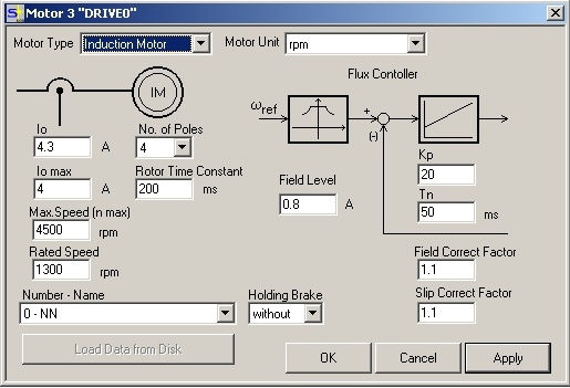
Fig. 1: Setup Software screen page "Motor"
Feedback
Instead of using standard feedback devices, sensorless operation is possible, too. Because of the motor current based speed encoding with sensorless technics, the real velocity can deviate from the commanded speed due to the slip. The rotation direction of the motor cannot be supervised with the feedback information. Change of two motor phases results in a change of the rotating direction without generating a fault message.
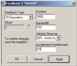
Fig. 2: Setup Software screen page "Feedback"
Current
Setting of the current controller is similar to a "standard" motor. KP must be increased with enabled servo amplifier (OPMODE 0, Enable = 1) from0.5 in steps of 0.5, until the motor starts whistling. Now the value must be decreased by approximately 20%
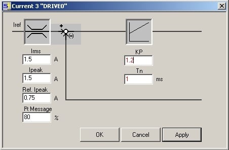
Fig. 3: Setup Software screen page "Current "
Speed
A high KP value in the speed controller is the basis for small speed deviation. Increasing the value of PID-T2 allows increasing of KP. Possible error message "Overspeed" (F08) in case of high motor capacity can be avoided by increasing the filter time constant T -Tacho.
After increasing PID-T2 you can increase KP in the speed controller. Principle for PID-T2: as high as possible to avoid oscillation and as small as possible if no further KP increasing is possible. If the coupled load changes, the KP value must be adapted.
The speed controller ramps must be set to relatively high values. If the values are too small, the motor runs rough. Values of 500ms and larger are ok.
Attention!
The value KP may only be increased by 20% steps (Example: 1 to 1,2 or 10 to 12) up to the vibration limit. Then the value must be reduced by 10%. With high KP values, the PID-T2 value may be decreased in small steps only.
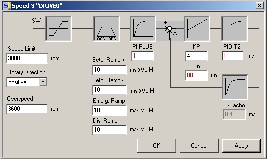
Fig 4: Setup Software screen page "Speed"
Examples (oscilloscop)
Actual speed Actual current Current set point
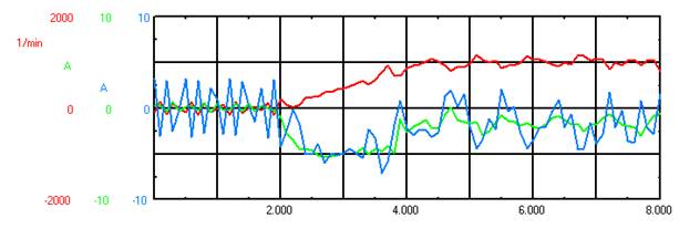
Fig 5: Badly tuned servo amplifier
Actual speed Actual current Current set point
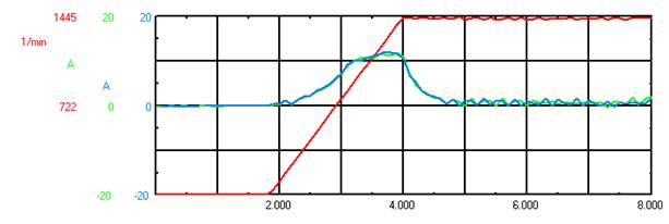
Fig. 6: Well tuned servo amplifier
