


 Home >
 Knowledge Base >
 Community >
 Downloads >
Commissioning AKD
The following provides brief explanations of the most important points for AKD commissioning and also goes into more detail on the key issues which need to be taken into account:
Basic settings of the AKD
Before the first controller parameters are set, the parameters should first be reset to factory default settings prior to the initial commissioning. This is done using the "Restore factory settings" button in the "Load/save parameters" tab.
Motor and feedback selection
Kollmorgen motors and feedback systems with memory
For feedback systems with internal memory (SFD, EnDat, BiSS...), the motor and the feedback system are read out directly from the feedback system. For this to work, the automatic motor selection option must be activated in the "Motor" tab and both the automatic motor selection and automatic feedback system identification option must be activated in the "Feedback 1" tab.
Kollmorgen motors and feedback systems without memory
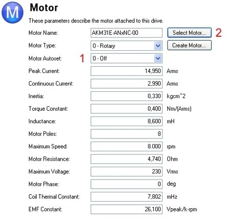
If the Kollmorgen motor employs a feedback system without memory, the automatic mode selection option (1) must be deactivated in the "Motor" tab. The new screen for selecting the motor is then opened by pressing the "Select motor" button (2).

The motor series can be used to select the various Kollmorgen motors (3), including windings, brake options and feedback system.
Third-party motors
When commissioning third-party motors, users should follow the same procedure as when selecting motors manually. The "Custom Motors" button (4) can be used to enter a user-defined motor.

The coil thermal constant value is often not available for all motor options. For this reason you can use the calculation given in the following link:
https://www.kollmorgen.com/en-us/developer-network/coil-thermal-constant-motorctf0/
Once all the necessary motor parameters have been entered, it is a good idea to export the new motor via the "Export" button.
Checking the feedback systems
Users can use the "Feedback 1" tab to check that the correct feedback system has been selected and set up accordingly. When the motor shaft is turned, the display must move the same distance and in the same direction.

Correct connection of the motor phases
Special characteristics for systems that require wake and shake
Prior to checking the correct connection of the motor phase, the automatic commutation angle calculation (w&s) must be executed for the test.
This is done on the terminal using the following commands:
DRV.MEMADDR CWakeAndShake.ws_state.U8
DRV.MEMDATA 0
Important: after checking the phase position, the W&S algorithm needs to be activated again:
DRV.MEMADDR CWakeAndShake.ws_state.U8
DRV.MEMDATA 1
Checking the phase position
First of all, the number of motor poles and also the motor phase must be read out and then set to a value of 0:
      MOTOR.POLES (read out value)
      MOTOR.PHASE (read out value)
      MOTOR.POLES 0 (set value to 0)
      MOTOR.PHASE 0 (set value to 0)
The controller must then be put into torque mode and subsequently enabled
      DRV.OPMODE 0
      DRV.EN
Important: W&S must not start at this point (otherwise the deactivation, as described above, has not worked)
Specifying a setpoint current (here for example 0.8 A):
      IL.CMDU 0.8
      -> the motor must engage in a preferred position
      -> then read out the current position (PL.FB)
      -> read out the current phase position (MOTOR.PHASE)
Step-by-step commutation angle increase:
Increase the MOTOR.PHASE in steps of 60 degrees
Read out the PL.FB
As the motor phase (MOTOR.PHASE) increases, the value for the position (PL.FB) must also increase.
If the value of actually gets smaller despite the increase in the motor phase, the motor phases must be swapped.
Once the test has been successfully completed, the current must be reset to zero and the controller disabled.
      IL.CMDU 0
      DRV.DIS
Reset the motor poles (MOTOR.POLES) and motor phase (MOTOR.PHASE) to their old values and, if necessary, also reactivate W&S.
Setting up W&S
The commutation angle is determined using the wake and shake method.
Back to top