Home >
 Knowledge Base >
 Community >
 Downloads >
Controlling Two Motors with AKD Dual Feedback Support
Dual feedback support allows the AKD drive to switch between two different motors. Only a simple three phase contactor is needed to switch the motors' phases. Note it is possible to connect and switch motors with different feedback types and different motor types.
This uses a contactor to switch between Motor 1 and Motor 2, and uses the two feedback ports (Feedback 1 on X10 and Feedback 2 of X9) to support the feedback for each motor.
The supported motor types are:
- Permanent magnet brushless motor
- Open loop induction motor (V/F)
- Closed loop induction motor
Supported feedback for first motor (X10):
- Resolver
- SFD
- SinCos Encoder BiSS
- SinCos Encoder ENDAT 2.1
- SinCos Encoder ENDAT 2.2
- SinCos Encoder Hiperface
- Sine Encoder + Hall
- Sine Encoder (Wake&Shake for brushless motor)
- Incremental Encoder + Hall (COMCODER)
- Incremental Encoder (Wake&Shake for brushless motor)
- BISS-C Renishaw
- Sensorless (V/f induction motor only)
Supported feedback for second motor (X9):
- Incremental Encoder + Hall (COMCODER)
- Endat 2.2 (data-only)
- Incremental Encoder (Induction motor only)
- Sensorless (V/f induction motor only)
An external controller connected to the AKD can be used with any of the supported fieldbuses to handle the parameter changes when the motors are switched.
To switch to the desired motor:
- Disable the drive.
- Switch the motor phase contactor to connect the desired motor.
- Set the parameters IL.FBSOURCE VL.FBSOURCE PL.FBSOURCE to 0 (First motor) or 1 (Second motor)
- Change all the other relevant motor parameters (motor type, gains, current limits, etc.)
WARNING! Before changing any parameters and switching the contactor, ensure that the AKD drive is disabled. Removing the STO signal should help prevent error during switching of the motors.
Note: Even if the motor is not selected its position is tracked and it is available as soon as the motor will be selected.
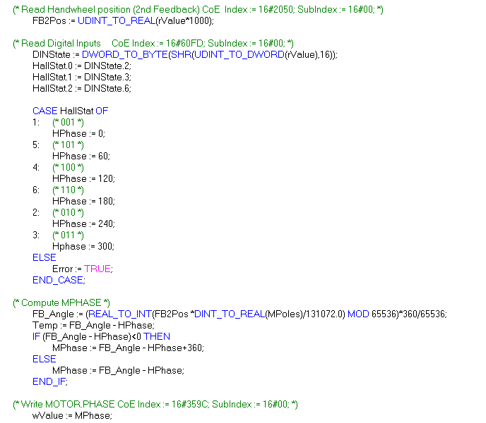
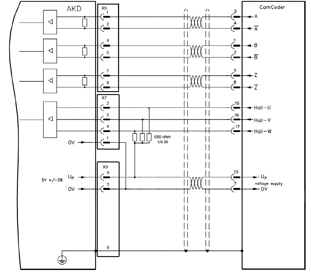
Incremental Encoder + Hall (COMCODER)
If the second motor has a COMCODER feedback, the Hall sensor signals must be connected to the X7 connector according to the following diagram:
When the second motor is selected the external controller must handle the motor phase alignment with the following procedure:
- Read Hall values on DIN-3, DIN-4, DIN-7.
- Determine Rotor angle (electrical, R_ANGLE) from Hall values:
| Angle | DIN-& | DIN-4 | DIN-3 |
|---|---|---|---|
| Illegal | 0 | 0 | 0 |
| 0 | 0 | 0 | 1 |
| 60 | 1 | 0 | 1 |
| 120 | 1 | 0 | 0 |
| 180 | 1 | 1 | 0 |
| 240 | 0 | 1 | 0 |
| 300 | 0 | 1 | 1 |
| Illegal | 1 | 1 | 1 |
- Determine feedback angle, the formula is:
FB_ANGLE = MOD((FB_POSITION*POLES)/131072,65536)*360/65536 where:
FB_POSITION is 32-bit position of secondary feedback
POLES is the number of motor poles = 2x the number of pole pairs
- Subtract FB_ANGLE – R_ANGLE, if negative add 360.
- Set MOTOR.PHASE to this value.
The following is a short example of how to compute the motor phase just after the motor: