


 Home >
 Knowledge Base >
 Community >
 Downloads >
Real-Time AKD Current Limits Change Using KAS
General Info
In many cases the AKD default peak currents have to be changed. There are several ways to do this, but not all are executed quickly and real-time. If AKD is working in standalone mode the easiest way is to declare the function 21 - Current limitation combined to one or more digital inputs.

This has the limitation of the number of digital inputs available, and of the value of current limit (Param) that have to be a constant. In addition the value is applied at both the positive and negative limit indifferently.
If a non real-time field bus is available, e.g. ModBus TCP/IP, ProfiNet or EthenetIP, it's possible to change the current limits, but this operation is quite slow. Other field buses like CANOpen or EtherCAT allow to reach a faster and real-time change.
Let's see how to do this with KAS and EtherCAT.
How to do this in KAS
Inside KAS it's possible to change AKD current limits using three methods:
- Method 1: using the function DriveParamWrite
- Method 2: using the function ECATWriteSdo
- Method 3: mapping the current limits as PDO
The first two modes are quite slow because they use the EtherCAT mail box. Being non-deterministic this writing takes about 50 EtherCAT cycles (50ms if the cycle is 1ms).
The third mode is the fastest: it's very easy to map both positive and negative current limits inside KAS adding one Rx PDO.
Method 1: DriveParamWrite
Values are given in A.

Method 2: ECATWriteSdo
Values are given in mA.

Method 3: mapping the current limits as PDO
This mode is the fastest way because PDOs are exchanged every EtherCAT cycle (KAS's minimum cycle time is 250us).
- Double-click on the AKD drive in the Project Explorer tree and open the PDO Editor window:

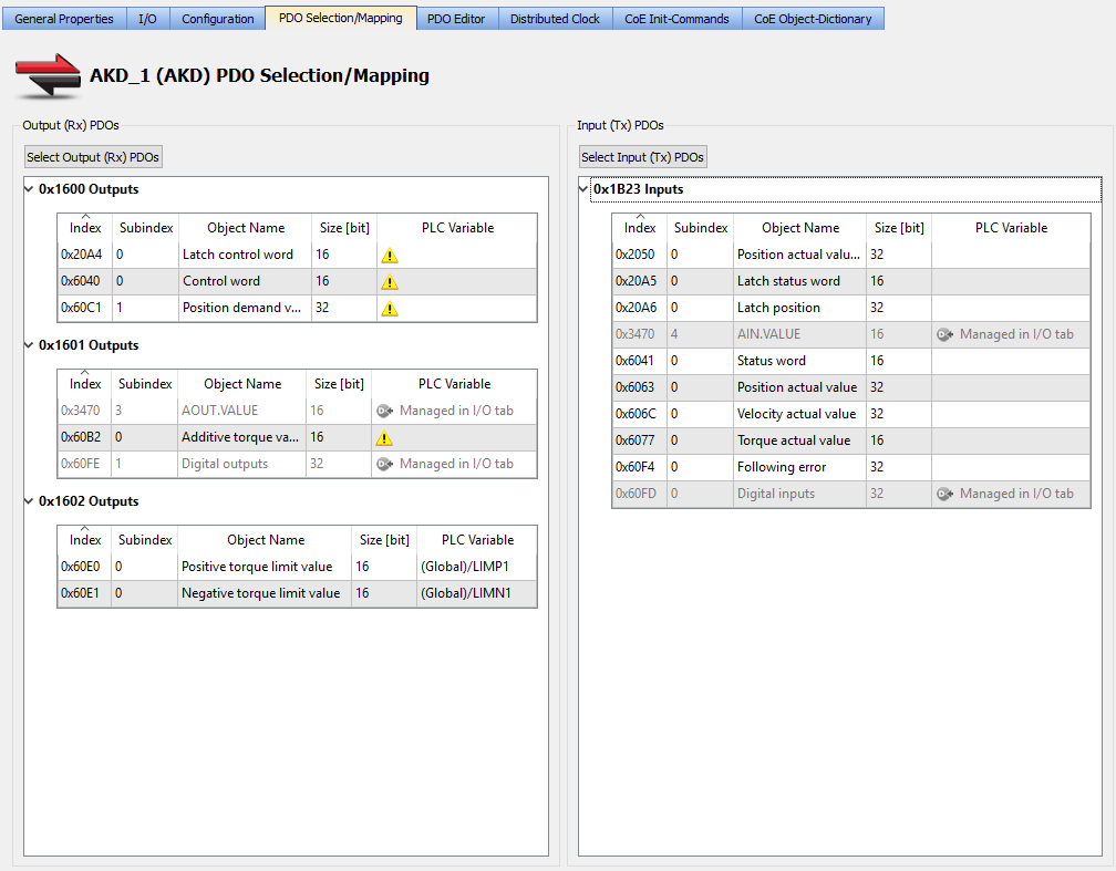
- Under Output (Rx) select the Index 0x1602, click on Add Object and select both CoE Objects 0x60E0/0 and 0x60E1/0.
- Then open the PDO Selection/Mapping window, click on Select Output (Rx) PDOs and flag the PDO Index 0x1602

- Once done, right-click on PLC variable at raw 0x60E0, Map to a defined variable or create a new one (type var UINT).
- Repeat this for 0x60E1. In the example 0x60E0 is mapped to the variable LIMP1 and 0x60E1 is mapped to the variable LIMN1.
By PLC code the writing to LIMP1 or LIMN1 will change IL.LIMITP and IL.LIMITN correspondingly. The values are given per thousand (1°/°°) of rated AKD current.
The attached two axis example includes a simple Control Panel to change these limits.

