


 Home >
 Knowledge Base >
 Community >
 Downloads >
S700 Safety: Safety Door Supervision
General
The following documents are important for an understanding:
- Operating instructions "PNOZ mm0p" and "PSEN cs2.1p" (download area of the international Internet site of Pilz www.pilz.com)
- Operating instructions S701...724
- Operating instructions for Safety Card S2
Products used:
- PNOZ mm0p (Pilz)
- S700-S2 (Kollmorgen)
- AKM Motor (Kollmorgen)
- Motor cable, 5 m (Kollmorgen)
- Feedback cable (Hiperface) 5 m (Kollmorgen)
- PSEN cs2.1p (Pilz)
- PNOZmulti Configurator (Pilz)
- SafetyGUI (Kollmorgen)
Example Application
The example shows the implementation of a safety door application with a PSENcode, a PNOZmulti Mini and an S700 with built-in S2 safety card.
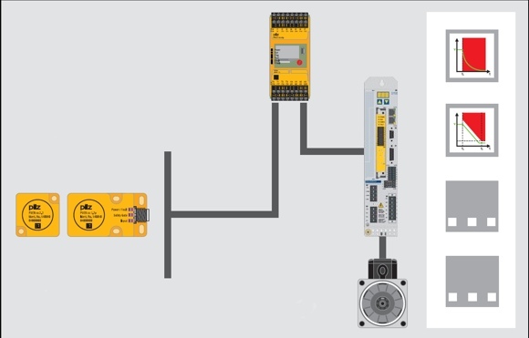
The safe control and analysis of the signals is performed by the
safety door function module from the element selection (input elements).
Safety door monitoring function
The control monitors the safety door switch (S5) via the application program. An FS function module safety door is assigned to the safety door switch. This FS FM detects whether the assigned safety door switch has been activated, but also incorrect input signals, contact synchronisation time-out, etc.
If the safety door switch is activated or an error occurs, the enable output of the FS FM is immediately reset. The enable output is also reset for a STOP of the PNOZ and when switching on the PNOZ.
The signal of the enable output activates the function SS2 of the safety card with a falling edge at input SS2 of the safety card. If the configured limits of the SS2 function are violated, the drive switches to STO.
It should be noted here that a holding torque is no longer available with STO and corresponding additional measures must be taken to ensure that this behaviour does not lead to a dangerous situation (e.g. with suspended loads). Based on an entry in the error stack, it can be determined why the enable output was reset.
The acknowledgment of the error is dependent on the operating mode set at the FS FM. In this application example, the FS FM is parameterised in such a way that an acknowledgment (S6) at the FS FM must occur in the following situations for the output parameter to be set again:
- during restart (PNOZ switched on/off),
- during startup (STOP-RUN transition of PNOZ), or
- after closing the safety door.
Caution
Even if the safety door function is configured as self-acknowledging, a PNOZ restart or closing the safety door may not effect a direct startup of the machine without any further conditions.
Wiring of the safety card
PNOZmulti outputs:
SS1 Activate : Safe stop 1
SS2 Activate : Safe stop 2
Reset : To reset the safety card after an error
To operate the safety card, it is mandatory that the signals SS1 and Reset are applied. These two inputs initiate a reset of the safety card. The Reset button (S3) at the PNOZmulti initiates the required signal sequence for the reset at the inputs SS1 and Reset of the safety card.
Remove the error and observe
- the error messages in the error stack.
- the LED display.
1. Switch the two inputs SS1 Activate and Reset to 0 V
- The safety card executes the safety function SS1 (Safe Stop 1) and changes to the "STOP" state. The "FAULT" LED flashes.
2. Switch the two inputs SS1 Activate and Reset to 24 V.
- The safety card changes to the "STARTUP" state. The device and the safe pulse inhibitor are tested. The "RUN" LED flashes.
- The safety card changes to the "RUN" state. The 'RUN' LED is permanently lit.
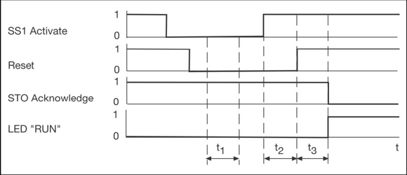
- t1 : at least 2 ms time while SS1 Activate and Reset have to have a "0" signal
- t2 : switching interval SS1 Activate – Reset
- t3 : approx. 2 s startup time of safety card
- SS1 Activate : input for safety function SS1
- Reset : input for SIL3 and Reset
- STO Acknowledge : output for acknowledgment signal of safety function STO
- "RUN" LED : system is operational
The remaining number of outputs is dependent on the number of safety functions configured on the safety card.
PNOZmulti inputs:
Reset : Initiates a reset of the safety card.
Ready : Reads the operational readiness of the safety card.
STO_ACK : STO activated.
Inputs for initiating the safety functions:
Application-dependent.
Input circuit safety considerations
- A cross circuit between the input circuits within a sheathed cable is recognised as an error by PSEN cs.
- A short circuit between 24 VDC and an input circuit is recognised as an error by PSEN cs.
- If the switch-off is performed via the inputs of PSEN cs, then the outputs can only be switched on again after both safety inputs have been blocked at the same time (partial activation inhibitor).
Motion Control safety considerations
- No dangerous situations may occur from braking ramps of SS1/SS2 and overtravel times.
- A perfect mechanism at the drive (overdimensioning) is assumed (exclusion of errors for a shaft break).
- The operator must ensure that the function of the safe pulse inhibitor is tested periodically by triggering the safety functions SS1 or STO, after 8 hours at the latest:
- with an operational restart after triggering the safety function SS1 or STO
or
- with a restart after triggering the safety function SS1 by the operator (see operating instructions).
Total application safety considerations
- The PNOZmulti and the combination of S700 / S2 safety card must be installed in the same installation space to rule out a short circuit between 24 VDC and a safety input of the card.
- An error in the PNOZmulti Mini or the combination of S700 / S2 safety card does not lead to a loss of the safety function.
Safety characteristic data
| Safety function according to EN ISO 13849-1 Safety-related control function (SRCF) according to EN 62061 |
Performance Level according to EN ISO 13849/1 |
Safety integrity level according to EN 62061 |
Safety-based parts of the control |
| Switching off a machine if a safety door is open. | PL d | SIL 2 | Sensor (PSEN cs2.1) Input (PNOZ mm0p) Input (PNOZ mm0p) Logic (PNOZ mm0p) Output (PNOZ mm0p) Actuator (S2 safety card) |
Prerequisites:
| Description | Identification | |
| Failure due to a common cause (CCF): | Requirements are considered fulfilled, β=2% (must be checked during implementation) | |
| Service life / Proof test interval | 20 years | |
Pease observe additional requirements of EN ISO 13849-1 (e.g. requirements for avoiding systematic failures) and EN 62061 (e.g. requirements for systematic safety integrity).
The calculation of the performance level is valid only with an AKM motor.
Circuit diagrams
PDF file, 7 pages
References
Pilz application document "1002085_DE_01": Safety door monitoring on PMCprotego DS with PNOZmm0p
Back to top