Home >
 Knowledge Base >
 Community >
 Downloads >
Tuning Rotary Direct Drives
Valid for S400, S600
General
Motors with special electrical or physical attributes need special setting, especially with parameters, which are usually unused in other applications.
This application note explains the special handling of these parameters, a generally valid statement to parameter values cannot be done, because motors and application can extremely differ.
Due to different calculation basics it is possible, that motors from different manufacturers will need different setting and it is necessary to tune a motor again, when the load is added.
Tuning is shown with a direct drive.
Special: Motor is mounted on a pillar that allows torsion.
Tuning
Feedback Test
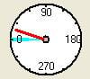 Feedback should be tested (screen page Monitor) with disabled amplifier (no power supply). Clockwise rotation of the motor shaft must result in a clockwise rotation in the display and in increasing position values.
Current Controller
Setup of the current controller is similar to a standard motor. You can use the ASCII command CTUNE. Alternatively the KP value can be evaluated by testing.
KP value (parameter MLGQ) must be increased in steps of 0.5 starting with 0.5 with enabled amplifier (OPMODE 0), until the motor starts whistling. Now the value must be reduced ba approx. 20%.
TIP:
Peak current should be limited to a low value to reduce the risk of damage. This value can be increased step by step depending on the tuning process. Ipeak value must be so high, that the motor is able to surmount friction.
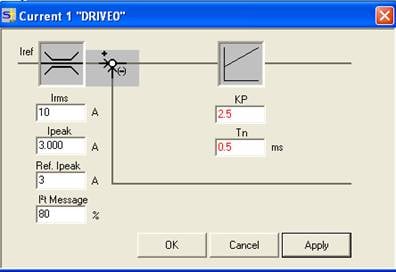
Figure 1: Screen page Current Controller (Drive.exe, S600)
In this case it's better to switch off the speed observer (OBSERVER). Now you can set the T-TACHO parameter in the speed controller.
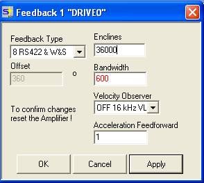
Figure 2: Screen page Feedback (Drive.exe, S600)
Speed Controller
In this application some tuning was necessary. Goal: inreasing speed controller's KP to get a stiff axis.
By increasing PID-T2 to 30 (that's a real large value) and T-TACHO to 2 the torsional vibrations of the pillar are filtered. Now KP can be increased from 70 to 600.
The very high KP value is typical for direct drives.
The KP value (parameter GV) should be increased in steps of 20% until the oscillation level is reached. Then the value must be reduced by 10%. Decreasing or increasing of PID-T2 must only be done in small steps.
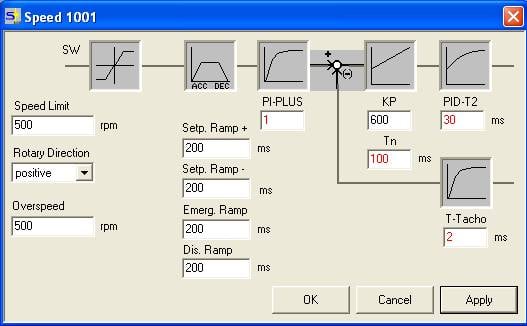
Figure 3: Screen page speed controller (Drive.exe, S600)
Adjustment to load mass
KP value must be adjusted, if the driven load changes.
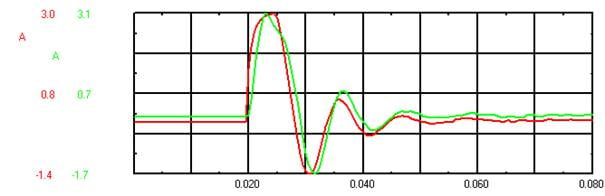
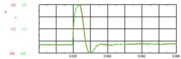
Measurements for tuning
Current I_cmd and I_act . 10ms time base. Response to speed step from 0 to 1000.
Badly tuned current controller:
Well tuned current controller:
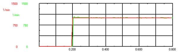
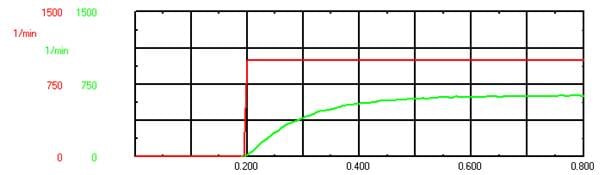
Speed n_cmd and n_act values. 100ms time base. Response to speed step from 0 to 1000
Badly tuned speed controller :
Well tuned speed controller: