


 Home >
 Knowledge Base >
 Community >
 Downloads >
Expansion card IO-14-08
Usable with S300, S600, S700
General
The -I/O-14/08- provides you with 14 additional digital inputs and 8 digital outputs. The functions of the inputs and outputs are adjustable with the setup software.
The I/Os are used to initiate the motion tasks that are stored in the servo amplifier and to evaluate signals from the integrated position control in the higher-level control system.
The functions of the inputs and signal outputs correspond to the functions that can be assigned to the digital I/Os on connector X3. All inputs and outputs are electrically isolated from the servo amplifier by optocouplers.
The command OPTION delivers a code for the built-in expansion card.
Expansion card
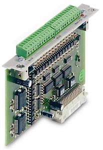
Front cover

LEDs
Two LEDs are mounted next to the terminals on the expansion card. The green LED signals that the 24V auxiliary supply is available for the expansion card. The red LED signals faults in the outputs from the expansion card (overload of switching components, short-circuit).
Technical data
| Control inputs | 24V / 7mA , PLC-compatible, IEC 61131 |
| Signal output | 24V / max. 500mA , PLC-compatible, IEC 61131 |
| Supply inputs, to IEC 61131 | 24V (18 ... 36V) / 100mA plus total current of the outputs (depends on the input wiring of the controls). The 24V DC voltage must be supplied by an electrically isolated power supply (e.g. with isolating transformer). |
| Fusing (external) | 4 AT |
| Connectors | Mini Combicon, 12 pin, coded on PIN1 and 12 |
| Cables | Data – up to 50m long : 22 x 0.5 mm², unshielded, Supply – 2 x 1mm², check voltage drop |
| Waiting time between 2 motion tasks | depends on the response time of the control system |
| Addressing time (minimum) | 4ms |
| Starting delay (maximum) | 2ms |
| Response time of digital outputs | max. 10ms |
Connector assignments
The functions are adjustable with the setup software. In the table below the default values are described.
Connector X11A
| Pin | Dir | Default function | Description |
|---|---|---|---|
| 1 | In | A0 | Motion block number, LSB |
| 2 | In | A1 | Motion block number, 21 |
| 3 | In | A2 | Motion block number, 22 |
| 4 | In | A3 | Motion block number, 23 |
| 5 | In | A4 | Motion block number, 24 |
| 6 | In | A5 | Motion block number, 25 |
| 7 | In | A6 | Motion block number, 26 |
| 8 | In | A7 | Motion block number, MSB |
| 9 | In | Reference | Polls the home switch. If a digital input on the base unit is used as a home input, then the input on the expansion card will not be evaluated. |
| 10 | In | F_error_clear | Clears the warning of a following error (n03) or the response monitoring (n04) |
| 11 | In | Start_MT_Next | The following task, that is defined in the motion task by “Start with I/O" is started. The target position of the present motion task must be reached before the following task can be started. The next motion block can also be started by an appropriately configured digital input on the base unit. |
| 12 | In | Start_Jog v= x | Starts the "Jog Mode" with a defined speed. “x" is the speed saved in the servo amplifier for the function "Jog Mode". A rising edge starts the motion, a falling edge cancels the motion. |
Connector X11B
| Pin | Dir | Default function | Description |
| 1 | In | MT_Restart | Continues the motion task that was previously interrupted. |
| 2 | In | Start_MT I/O | Starts the motion task that is addressed by A0 - A7 (connector X11A/1...8). If no motion task is addressed, a reference run is started. |
| 3 | Out | InPos | When the target position for a motion task has been reached (the InPosition window), this is signaled by the output of a HIGH signal. A cable break will not be detected. |
| 4 | Out | Next-InPos | The start of each motion task in an automatically executed sequence of motion tasks is signaled by an inversion of the output signal. The output produces a LOW signal at the start of the first motion task of the sequence. The form of the message can be varied by using ASCII commands. |
| PosReg 0 | Can only be adjusted by ASCII commands/setup software. | ||
| 5 | Out | F_error | A LOW signal indicates that the position has gone outside the acceptable following error window. |
| 6 | Out | PosReg1 | default: SW limit 1, indicated by a HIGH signal |
| 7 | Out | PosReg2 | default: SW limit 2, indicated by a HIGH signal |
| 8 | Out | PosReg3 | Can only be adjusted by ASCII commands/setup software. |
| 9 | Out | PosReg4 | Can only be adjusted by ASCII commands/setup software. |
| 10 | Out | PosReg5 | Can only be adjusted by ASCII commands/setup software. |
| 11 | - | 24V DC | Supply voltage for output signals. |
| 12 | - | I/O-GND | Digital GND for the control system. |
Documentation
Data sheets for the expansion card can be found via File Selector, set document type filter to "Add On Document".
Back to top