


 Home >
 Knowledge Base >
 Community >
 Downloads >
Setup of HALL feedbacks
Valid for S300, S700
Hall Signal Testing

Oscilloscope (Setup Software)
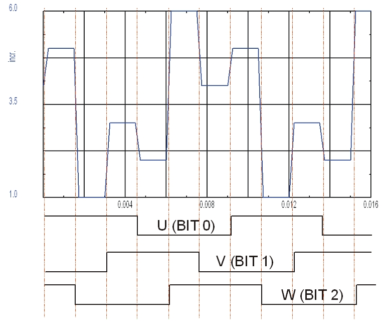
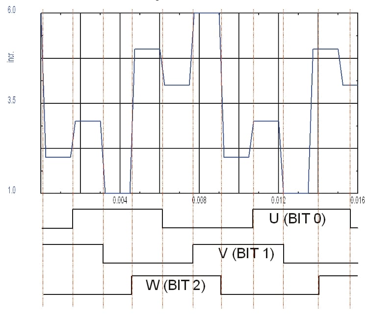
Use the oscilloscope of the setup software. Select "user defined" for the channel and measure SR_HALL:
|
CW rotation, signals U - V - W |
CCW rotation, signals W - V - U |
 |
 |
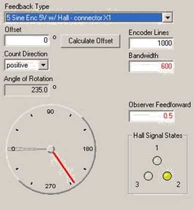
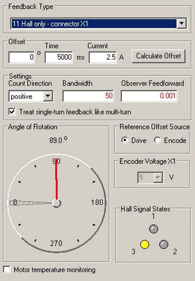
Feedback Monitor (Setup Software DriveGUI)
| Feedback Type 15, ComCoder (Hall Sensors with incremental encoder) |
Feedback Typ 11, Hall sensor (Hall sensor only) |
 |
 |
Change rotation direction
The rotation direction of the Hall Sensors can be inverted with S300/S700 by changing the parameter HALLDIR (refer to Motion direction - Parameters). After changing HALLDIR the parameter MPHASE must be adjusted as well.
Note: setup DIR if HALLDIR has been changed: HALLDIR = 1 --> DIR 20 / 21 --> DIR 85 / 84
Check the Feedback Function
| Core color | Blue | + | + | — | — | ||
| Brown | — | + | + | — | |||
| Violet | — | — | + | + | |||
| Motor phase | U | + | + | — | — | ||
| V | — | + | + | — | |||
| W | — | — | + | + | |||
| Hall | 1 (U) | L | ⇔ | H | H | ⇔ | L |
| 2 (V) | ⇔ | L | L | ⇔ | H | H | |
| 3 (W) | H | H | ⇔ | L | L | ⇔ |
Symbol ⇔ means, that with minimal rotation of the motor axis the signal changes.
Setup of unknown Hall motors
The ASCII commands must be send with a terminal software.
| Task | ASCII | Value | Function |
|---|---|---|---|
| Evaluation of the Hall rotation direction HALLDIR |
MPOLES OPMODE T MPHASE |
0 2 0.5 x x = (30, 60, ..., 330) |
No of motor poles = 0 OPMODE Torque Digital Constant Current Setpoint (e.g. 0.5 A) Phase offset of the feedback system (related to the motor phase) Increase phase offset in steps of 30 check the Hall signals with the parameter M SR_HALL. Example: Hall sequence: 1,5,4,6,2,3,1 then the rotation direction is positiv (HALLDIR 0), Setting HALLDIR: |
| Evaluation of the rotation direction of the position encoder PFB |
PFB |
Rotate the motor axes clockwise. Observe the position value with the command PFB. If PFB decreases, you must invert the direction with the command DIR. The DIR variable defines the counting direction of the feedback unit. |
|
| Evaluation of commutation angle | MPHASE MSG PFB |
90 2 |
Important: Multiply the angle with the number of pole pairs, e.g. 153.237 x 3 = 459.711. Subtract 360 until the result is a value between 0 and 359. The rounded value is the value for MPHASE: Example: |
| Fine Tuning MPHASE | ZERO | Fine tuning for MPHASE |
Controlling in low velocity range for Feedback Type 11, Hall ONLY
The drive receives a new position information by hall-sensor every 60° (electrically).
Assumed the motor has 6 poles, one mechanical revolution = 3 electrical revolutions.
This means, every 20° we receive a new Hall-Position: 0°, 20°, 40°, 60°, ... , 340°.
This information is not enough for a reasonable controlling in the lower speed range. For this reason there are two controlling-methods, which are applicable depending on the velocity:
- In the lower speed range (velocity is lower than SLISWITCH) the motor is controlled sensor-less. ,
- Above the velocity in SLJSWITCH the drive uses the position information from the hall-segments (commutation, velocity, Position).
The following concepts of Controlling for velocity range below SLJSWITCH are integrated in the S300 / S700 servo amplifiers:
- Stepper Mode, U/F operation: The drive operates like a stepper drive, U/F curve. This mode is activated by SLMODE 1.
- HF Mode (High frequency injection): This mode is activated by SLMODE 0. It just exists for compatibility reasons and will not be developed further.
ASCII Parameters
- SLMODE: With this parameter you can choose between Stepper Mode (U/F) or HF function. This function is used in the lower speed range only.
- SLMODE 0: Enable HF mode. In this mode TEN must be zero. If not, no torque will be applied!
- SLMODE 1: Enable stepper mode(U/F). This mode is recommended.
- TEN: is set internally by firmware if SLMODE =1. Depends on velocity feedback and SLMODE:
- TEN 0: just in SLMODE 0.
- V < SLJSWITCH HF active.
- V > SLJSWITCH Hall-information is used for controlling .
- TEN 1: V < SLJSWITCH: U/F active.
- TEN 2: V > SLJSWITCH: Hall-information is used for controlling.
- TEN 0: just in SLMODE 0.
- SLJSWITCH: Threshold value for lower speed range. Default 500 RPM.
- SLTSWITCH: Transition time from lower speed range to higher speed range in ms. Default value: 200ms. The motor continues using SLMODE, before hall-sensor based controlling is activated.
- DRVCNFG4 Bit11: Improved calculation of the current speed in hall-only mode. This function is not active by default (for compatibility reasons), but should be used in new hall-only applications.
OPMODE 2/3 Torque Command
Analog or digital torque command do not work with HALL ONLY. The motor delivers torque with enabled power stage even if the current setpoint is zero, because in small velocity range the U/F or HF function is active!
Commutation Detection ZERO, MPHASE
MPHASE is calculated in OPMODE 2 by the ZERO function, similar to other feedbacks. Hall ONLY only sends one pulse every 60° electrical, therefore MPHASE is precise to ±30° electrical.
The servo amplifier commutates "sensorless" in low velocity range and use MPHASE & feedback signals for commutation in case of velocity higher than SLJSWITCH.
Fast setup
DRVCNFG4 bit11= 1
SLMODE 1                            //TEN is controlled automatically, if SLMODE is 1. TEN should be 0 in case of SLMODE 0!
SLACCMAX 100 rpm/s                  //can be increased in Operation.
ACC=DEC=DECDIS=DECSTOP=500 rpm/s    //can be increased in Operation.
MRESBW 50                           //range 30 to 100
Back to top
