


 Home >
 Knowledge Base >
 Community >
 Downloads >
AKD Functional Safety Safe Stop using KSM SafetyPLC
Table of Contents
Hardware
Drive: AKD-B00306-NBAN-0000
Safety PLC: KSM 11-2 PN: 0000119
Cable: KSM CABLE SINCOS
Motor: AKM22C-ACGNAB-00
Cable: VF-SB447N-01
Cable: VP-508CFAN-03
Software: SafePLC KSM version 0.1.19-281-140731 dated 31JUL2014
Logic description
The Safe Stop operation involves the AKD performing a Controlled Stop function, disabling the output stage. The Safety PLC monitors the E-STOP button and drops the STO after a time delay, even if the motor has not stopped.
Timing Charts
Timing chart for normal operation

Timing chart for KSM fault

Reset logic timing chart

Wiring

The AKD’s STO input has a 3.8A inrush current spike when 24V is applied. The KAS relay output has a 2A max limit. Either a pilot relay or current limiting resistor is required to prevent damage to the KSM module.
Terminal diagram program

Encoder setup screen (Double click on feedback icon, top left of input block)

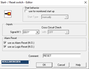
Example of input setup screen (E-Stop Button)

Example of RESET button setup screen
Example of relay output setup screen (CS_EN)

CFC program

Example of SSx block setup

Example of timer block setup

Notes
- “Time On” block is to delay the drive’s CS input until the STO has been turned on. 300mS or more is OK.
- The SSx block must receive an “Alarm Reset” after the SSx input has gone low. (No Alarm Reset input on the block. The reset function becomes automatic when the reset switch is programed as “Alarm Reset”) A simpler logic design would drive the STO and CS output high as soon as the ESTOP was reset. I wanted to force the operator to press the reset button, so I added some Flip-Flop logic.
- Critical drive parameters
DIN6.MODE 13 to setup digital input 6 as a CS input.
CS.DEC 10000 RPM/s
CS.TO and CS.VTHRESH to capture zero speed quickly without false triggers.
DRV.DISTO 400Ms (Max speed is 3000 RPM.  3000RPM/10000RPM/S = 300mS.)
MOTOR.TBRAKETO -1 (If there is a brake)
- Testing using the workbench scope
Normal operation; Green and Blue are motor velocity. Violet is CS EN input. Pink is STO input

Fault operation: (Colors are the same) STO is dropped and drive faulted

