


 Home >
 Knowledge Base >
 Community >
 Downloads >
HiperFace
HIPERFACE®
The High Performance Interface is the standard interface for SICK-STEGMANN motor feedback systems.This interface was specially developed for the requirements of digital drive control and offers the user standardised and simplified mechanical and electrical interfaces.
Features
- Only one electrical interface on the speed controller for all applications and only one type of cable between speed controller and motor feedback system
- Implementation of both low-end and high-end applications with only one electrical interface
- Hybrid interface from
- the analogue process data channel on which sine and cosine signals are transmitted differentially, with almost no delay
- the bidirectional parameter channel corresponding to the RS485 specification for transmitting absoluteposition information and various other parameters
- Only 8 wires
- Electronic type label for identification of the motor feedback and storage of drive-related information in the motorfeedback system
- Wide temperature range, high shock- and vibration resistance, immunity to electromagnetic interference and compact dimensions. The devices can be fitted inside the servo motor
- Analogue sine/cosine signals are available for speed control. These enable both high resolution for use at low speeds and sufficiently low signal bandwidth for the control of high speeds.
- Cable lengths up to 100 m.
- Standardised mechanical interfaces.
- The encoder shaft has a rigid link to the motor shaft, enabling high amplification factors to be used.
- Easily fitted in the servo motor. Axial and radial tolerances are compensated via a flexible stator coupling (also: torque support).
- The relationship of the absolute value to the mechanical shaft position can be electronically manipulated toadjust the commutation.
- For the position control of mechanically geared applications, motor feedback systems with the same physicaldimensions are also available as absolute multiturn units, for absolute positioning over up to 4096 revolutions.
HIPERFACE® motor feedback systems are a mix of incremental encoders and absolute encoders and combine the advantages of both encoder types.
Initially, the absolute value is only formed when the device is powered up and communicated – via the bus- enabled parameter interface according to the RS485 specification – to the external counter in the controller which, based on this absolute value, then incrementally counts on from the analogue sine/cosine signals.
The use of highly linear sine and cosine signals achieves the high resolution needed for speed control (the arc tangent is formated in the controller). Simultaneously, however, the signal frequencies to be transmitted remain relatively low. For example: 512 periods per revolution, even at a speed of 12,000 rpm, only produce a frequency of 102.4 kHz which can be easily transmitted, even over very long distances.
Design
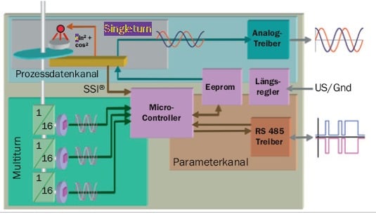
Fig.1
As is common for standard encoders, most motor feedback systems have an internal glass code disc as a measuring scale . Using the direct- light method, an infrared diode maps the code pattern on the disc onto a fully customised highly integrated circuit. The characteristic feature of the SinCos® motor feedback systems now is that, in addition to the absolute codetrack, there also is an incremental track producing sine and cosine signals.
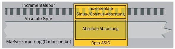
Fig.2
Usually, in a motor feedback system, 2n periods of sinusoidal and cosinusoidal signals are scanned. These signals are always available via the so- called process data channel, as real- time data. Parallel to this, the absolute position data is available via the parameter channel (RS485). It primarily serves to identify exactly one of these 2n periods.
Processing
HIPERFACE® defines the standardised electrical interface with only 8 wires:
- 2 x Supply voltage 7 … 12 V
- 4 x Incremental, differentially transmitted, sine/cosine signals
- 2 x Digital, bidirectional RS485 interface
A fully screened 8TP cable securely transmits the signals to the controller.
Supply voltage
At first glance it seems a disadvantage having to produce an additional, rather unusual supply of typically 8 V within the controller. This, however, ensures sufficient voltage supply to the HIPERFACE® motor feedback system even for long distances between drive and motor feedback system. More involved supplies, e.g. with sense cables, are not required.
RS485 interface
This interface can safely be described as industry standard. The physical interface requires a 130 Ω termination resistor, two biasing resistors and a standard RS485 transceiver.
The interface is configured to 9600 baud, as standard. In principle, the bidirectional RS485 interface is bus enabled; therefore, each communication from the Master, i.e. the control, begins with the slave address. Binary data transmission minimises the transmission times. Each protocol is completed with an easy to calculate XOR checksum. The end of the protocol is detected using a timeout control. The HIPERFACE® motor feedback systems have internal diagnostic functions and signal critical or faulty conditions monitoring within the response protocol.
SinCos® interface
The sine / cosine signals are transmitted fully differentially, their amplitude varying no more than 20% in all circumstances. Since this interface determines the actual performance of the speed controller, this part of the interface must be carefully developed.
The screen
The screen concept too is very important and has an influence on the achievable performance of the whole system. A large area screen applied to both sides, motor and control, should achieve the best results.
The high resolution (arctan interpolation)
There are many known methods for calculating the high resolution angle. The following method (see fig. 3) has proved a good compromise regarding code size and speed of execution:
- Reducing the calculation to the 1st octant (0...45°) by swapping and/or inverting the sine and cosine values,hence the following;
- Calculation of the division sin (x)/cos (x) always has a result < = 1.
- Table-based linearisation of the division result for approximation to the arc tangent function (32 bases approx.required).
- Backward transformation and expansion of the result in the octants determined under 1.
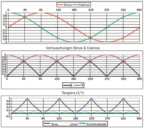
Fig.3 Arctan Interpolation
Synchronisation
The overrun or the flanks on the various transmission paths will, in reality, never occur at the exactly identical pointin time.This can be explained by the following effects:
- the absolute position is determined via separate code tracks and, therefore, differs slightly from the position interpolated from the analogue signals (see fig. 4). Therefore, this phase position can change by up to ± 4/32 of a period, within a turn.
- dynamic effects such as signal run times or different input filters
- hysteresis, e.g. within the comparator of the quadrature counter
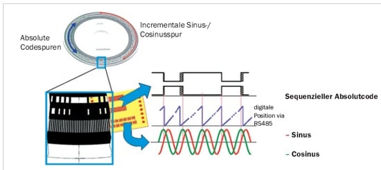
Fig.4
The synchronisation now describes a method which can compensate these effects within wide limits (± 1/2 period). This makes it possible, even at high speeds, to assign the analogue signals to a specific period. Consequently, the overlapping bits of two different pieces of position data are always oriented to the same valence,and the difference of the position values is then formed. If the two position values point to different periods, the position value with lower resolution is corrected in the direction of the smaller difference by ± 1 period.
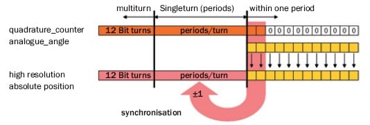
Fig.5
- quadrature_counter:
the position value also within the controller with a resolution of 4* number of periods - analogue_angle:
the angle calculated from the analogue signals within one period - absolute_position:
the absolute position read out via the parameter channel
Source
Hiperface Description, Sick/Stegmann, 8 010 701/2008-04-02, MD/3/50
