


 Home >
 Knowledge Base >
 Community >
 Downloads >
Implementing Extended Multiturn on KAS (Non-Binary Gear Box)
On a rotary application with absolute multi-turn feedback, it's possible to run over the feedback unwind. If the machine has a non-binary gear ration (e.g. 3:1), its period is not an integer divisor of the encoder period, allowing the position to not be the same after a power cycle. In other words, it may be shifted by the fraction of the ratio.
To avoid this situation the AKD Drive is capable to track and store the number of turn bits beyond the bits stores in feedback. This is made by setting the parameter FB1.EXTENDEDMULTITURN = 1. This setup secures that FB1 position (32-Bits) will always be the same after a power cycle, even in this non-binary gearbox situation.
Now, the EtherCAT position read by KAS is limited to 20-Bits, the 12-Bits used to store the number of turns is ignored. Taking this into consideration, even if the FB1.EXTENDEDMULTITURN allows the drive to store the number of turns, the information is disregarded by KAS.
To avoid this issue a function block has been developed. It reads the FB1.P from AKD, the number of turns is extracted and the unwinds is calculated.
Right after the network and motion engine get started, the function block is called and correct position according to the number of unwinds.
Attached is a .kas example. This uses the UDFB_AbsExtendedMultiturn applied to the Standard SFC Template, added to a step just after the routine go to running.
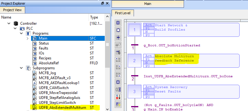
Understanding the UDFB_AbsExtendedMultiturn
The function block must be called right after the network is initialized, and is ready to be used with all programing languages (ST, SFC, FFLD and FBD).
Actions made by the UDFB:
- Sets FB1.EXTENDEDMULTITURN - 1;
- Sets FB1.PIN - 1048576;
- Sets FB1.POUT - 1;
- Sets FB1.PUNIT - 3 (PIN/POUT);
- Reads User Units per Rev;
- Reads Axis Rollover;
- Reads FB1.P;
- Calculate the number of revolutions and overflow;
- Calculate the new axis position;
- Changes the actual position of the axis to the new position;
FFLD Representation:
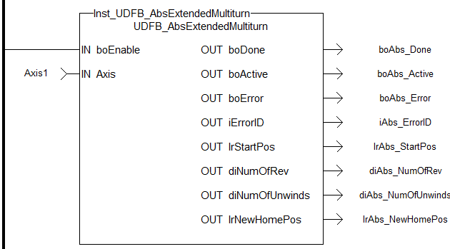
Inputs
IN_boEnable - BOOL - Enables de Function Block;
IN_Axis - AXIS_REF - Structure for specified Axis;
Outputs
OUT_boDone - BOOL - Motion profile calculated ;
OUT_boActive - BOOL - Calculating profile;
OUT_boError - BOOL - Signals that an error has occured within the function block;
OUT_iErrorID - INT - Specific Error number:
1 for Fault to Write FB1.EXTENDEDMULTITURN;
Check for a valid Feedback Type, the algorithm requires 12 multiturn bits;
4 for Axis Faulted;
OUT_lrStartPos - LREAL - Actual position before unwind ajustment
OUT_diNumOfRev - DINT - Number of revs base on FB1.P/(2^20);
OUT_diNumOfUnwinds - DINT - Number of overflow to +-2048 revlotions;
OUT_lrNewHomePos - LREAL - New absolute axis position after the calculation;
