Home >
 Knowledge Base >
 Community >
 Downloads >
Motor Phase Wiring - S300 or S700 to KBM with Non-Standard Connections
Application Note: Motor-Phasing/wiring: non-standard, S300 or S700 - positive feedback count with a CW rotation as viewed from the lead exit end, for KBM(s) motor.
S300 or S700 - drive to KBM(s) frameless motor, with non-standard connections.
For PDF format: S300 or S700 to KBM - Non-std Motor Phasing for Pos FB CW Rotation.pdf
A. Phase leads per the outline-drawing:
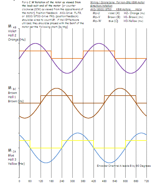
KBM-motor phasing is defined with a C.C.W. rotation of the rotor as viewed from the lead-exit end of the motor; this is a clockwise (C.W.) rotation, looking into the shaft/torque end-bell of most standard housed motors (Like: AKM, BH/MH, series motors). KBM-series wire label convention is meant to be the same as the AKM, BH/MH, series motors; but its specific wiring identification is most easily identified from the lead-exit end, due to it being frameless.
The S300 and S700 – drive, standard configuration of the phases: U,V,W, are with a C.W. rotation of the rotor as typically viewed from the torque end-bell (shaft end or mounting end-bell) of the motor, for a positive feedback count (this is the same direction in which the KBM(S) is phased: U,V,W).
The system standard is to connect: motor, to the Drive using the Drive’s phasing configuration, for drive phase U -> motor phase U, drive phase V -> motor phase V, etc.; however, for non-standard positive feedback count with a C.W. rotation of the rotor as viewed from the lead exit end, the motor-drive phase connections are most easily accomplished by labeling motor phases: U,V,W, to C,B,A; and connecting S300 or S700 – drive per the following information (similar to standard RBE’s phasing configuration). It is to this end, that this applications note has been written.
B. CONVENTION:
The non-standard electrical connections between the S300 and S700 -drive to KBM(s) - frameless motor for a positive feedback count, unless specifically stated otherwise, is based upon a C.W. rotation of the rotor as viewed from the lead-exit end of the motor, for a positive count direction of the position-loop. Hence the words: C.W. rotation of the rotor, will refer to this specific convention, through-out this document. In addition, if applicable, to help clarify one motor phase or Hall feedback signal, to another, an underlined last letter is utilized under the point of electrical reference; hence, phase-AB, reads: phase-A with respect to phase-B, leads B, by 120-degrees, with a C.W. rotation of the rotor); or where, a positive Hall-2 (H2) signal, also defined as Hab (Ha/drive-Hu)] for the defined convention), reads: Hall signal: H2 (Hab) is positive and in phase with motor’s Bemf, phase-A, with respect to motor phase-B, with a C.W. rotation of the rotor, viewed from the lead-exit end.
C. MOTOR TO DRIVE CONNECTIONS:
M-Violet (W) = phase: A= typical Kollmorgen cable: blue-wire = drive: AKD (U)....Hall(u) = Hu/Hab/ H2 (orange)
M-Brown (V) = phase: B= typical Kollmorgen cable: white-wire = drive: AKD (V)....Hall(v) = Hv/Hbc/H1 (brown)
M-Blue (U) = phase: C= typical Kollmorgen cable: black-wire = drive: AKD (W)....Hall(w) = Hw/Hca/ H3 (yellow)
M-Green/Yellow-strip GND/PE.
- Wire colors for a given motor-phase can be different than stated herein; so use the outline-drawing of the motor for the determination of the correct color of a phase with the specified rotation reference. Motor(M)-Violet [phase: A or W], Motor(M)-Brown[phase: B or V], & Motor(M)-Blue [phase: C or U], are common KBM motor series colors and, only represent the wire connections from the motor armature; consult the motor wiring document [outline, HD, or WD] for true wire colors, or connector pin-outs (if applicable).
- Hall phasing check: with a C.W. rotation of the rotor:
(a) H2 (Orange) or Hab (Ha/drive-Hu) should be high in phase with the Bemf of motor phase: AB;
(b) H1 (Brown) or Hbc (Hb/drive-Hv) should be high in phase with the Bemf of motor phase: BC;
(c) H3 (Yellow) or Hca (Hc/drive-Hw) should be high in phase with the Bemf of motor phase: CA.
- If the feedback device (resolver/ENDAT/Biss sine-encoder/Hiperface) needs to be aligned with the Bemf of the motor, please see FEEDBACK DEVICE ALIGNMENT, [below].
D. S300/S700 – feedback setup
From the specific human-machine-interface(HMI) drive software: S300/S700: DriveGUI.exe, go to the feedback dial and turn the motor’s rotor by hand in the C.W. direction as viewed from the lead-exit end/side of the motor [or C.C.W. from the other end]. (1) Drive - S300/S700 varible: PRD, should count up; if it is not counting up, switch two of the feedback wires and make it so it does count up! {Resolver:(sin(+) & sin(-), or Encoder: A & A-not, or Sine-encoder: Sin+ & Sin-} ---- For sine encoder utilization with serial transmission (ENDAT/BISS/Hiperface/etc.) - see SERIAL TRANSMISSION, [below].
E. FEEDBACK DEVICE ALIGNMENT:
- If feedback device alignment is required:
a. For the drive: S300/S700 – series, use the ZERO alignment procedure/feature within the ‘drive to PC’ software: DriveGUI.exe (S300/S700), or Drive.exe (S600), to establish commutation angle variable: MPHASE.
b. For manual setting [same as AKM]: Find the null-position via a 24-volt DC power source by connecting the (+) to motor-phase: A [W]; and, (-) to motor-phase: B [V]; if AKD set: MOTOR PHASE, = 0.0; NOTE: Allow motor-phase: C [U], to float (and not short to anything). [Based on published AKM data-pub.]
F. SERIAL TRANSMISSION:
- For sine encoder utilization with serial transmission (ENDAT/BISS/Hiperface/etc.), due to mechanical mounting orientation with respect to the motor armature it is possible to have the feedback counts go in the correct direction (sine-cosine communication working) and the serial transmission (ENDAT/Hiperface/etc.) not commutate properly for the communication of the motor. If this is the case, switch encoder sine connections with the cosine connections (positive-for-positive, negative-for-negative). This will allow the serial transmission Drive - S300/S700: PRD, to count in the correct/same direction and also present the communication data to the drive in the proper order; double check Drive - S300/S700: PRD, should count up, for a C.W. rotation of the rotor as viewed from the lead-exit end/side of the motor [or a C.C.W. rotor rotation from the other end of the motor].
a. Drive - S300/S700, serial transmission (ENDAT/BISS/Hiperface/etc.) feedback sine-encoders require an HSAVE command, in addition to a SAVE command, to save variables to/within the encoder.
b. Drive - S300/S700, for first time set-up:
1. Heidenhain ENDAT/BISS encoders require commands: SAVE, HSAVE, HSAVE, COLDSTART [note: the HSAVE must be done twice.].
- Stegmann Hiperface encoders, require commands: SAVE, HSAVE ERASE, HSAVE, COLDSTART [note: The HSAVE ERASE is to clear old/test data.]. The Hiperface encoder does not do mechanical alignment to a fixed angle like the ENDAT encoder can; thus, the drive’s MPHASE variable can and most likely will be, different between like motors; Thus the user/OEM/Customer must measure the MPHASE variable with the command: ‘ZERO’ and store it by the SAVE and HSAVE commands, for each system, on initial machine setup.
G. DIRECTION OF ROTATION PURSUANT TO THE COMMAND
Once the encoder transmission of the serial position feedback and the sine/cosine position feedback is in synchronization
(if applicable) and properly commutating motor, if the motor is not turning in the desired direction by the desired
Position command signal, user can reverse the motor’s direction by changing S300/S700-drive variable: DIR, as needed.
H. HALL COMMUNICATION:
Kollmorgen drives as well as most other drive manufactures reference the hall-effect/com-coder feedback (for initial communication on a power-up cycle) in phase with the Bemf of the motor [with Hall edges lining up with the Bemf line-line zero crossing] with Hall outputs going positive when the Bemf is positive, for the same direction of shaft rotation as the utilized convention for determining the motor phasing.
Hence, Kollmorgen motors with motor phases labeled: A, B, & C, such as Kollmorgen’s RBE-series/BM-series, typically utilize a C.W. (clockwise) rotor rotation convention for the determination of the motor phasing, as viewed from the lead exit end; thus, when the motor shaft/rotor is rotated in the same direction as the phasing convention (C.W. direction as viewed from the lead exit end), the appropriate Hall signals will be going positive with the Bemf of the motor and in phase with the Bemf of the motor.
In contrast: for the KBM-series the motor phases are labeled: U, V, & W, and the rotor rotation convention for the determination of the motor phasing is C.C.W., as viewed from the lead exit end; thus, when the motor shaft/rotor is rotated in the same direction as the phasing convention (C.C.W. direction as viewed from the lead exit end), the appropriate Hall signals will be going positive with the Bemf of the motor and in phase with the Bemf of the motor.
If this is your application, please see APPLICATION NOTE: S300 or S700 to KBM - std Motor phasing for Pos FB CCW rotation lead-exit-end U_V_W typical Blue - Brown - Violet.