


 Home >
 Knowledge Base >
 Community >
 Downloads >
AKD Controlled Stop and Holding Brake Timing
Description
Using a Controlled Stop input is the only way to do a controlled deceleration and control the timing of engaging/disengaging a holding brake. The hardware enable, STO, and software enable will engage/disengage a holding brake, but they will not apply the brake timing. There is an inherent delay during engaging a holding brake. If the brake timing is not applied in a vertical load application, the load will fall. Another danger with not applying the brake timing is when the motor is running at high speed when the drive is disabled. Without a controlled stop, the brake will engage while the motor is moving and subsequently damage the brake.
Configuration
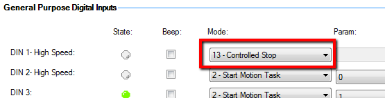
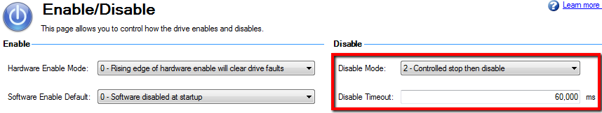
Configure any one of the digital inputs as Controlled Stop. Also configure the Disable Mode to #2 (Controlled stop then disable) in the Enable/Disable screen of Workbench.
To ensure that the drive completes a controlled stop and engages the brake, make the following settings:
| Parameter | Value |
|---|---|
| DINx.MODE | 13 (Controlled Stop) |
| DRV.DISMODE | 2 (Controlled stop then disable) |
| DRV.DISTO | long enough time to allow for deceleration and controlled stop timeout |
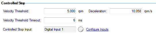
| CS.VTHRESH | 5 rpm (low enough to not damage the brake) |
| CS.DEC | decel rate fast enough to stop motor before the disable timeout |
| CS.TO | 6 ms (short time to engage the brake quickly after reaching the velocity threshold) |
| MOTOR.TBRAKEAPP | long enough to fully engage brake before drive disables |
| MOTOR.TBRAKERLS | time delay between enabling drive and disengaging the brake |
- Digital Input setting:

- Disable Mode settings:

- Controlled Stop settings on the Enable/Disable screen:

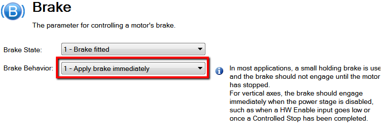
- Brake setting for a vertical axis or any axis being acted upon by an external force:
- Brake setting for a horizontal axis that is not being acted upon by an external force:

- Brake timing settings:
Functionality
Digital Input:
When the Controlled Stop input is turned off, the controlled stop function is activated. The Controlled Stop input is level triggered and normally closed.
Input On (closed circuit) = normal operation with the motor running
Input Off (open circuit) = controlled stop active, motor will be stopped and drive disabled
Deceleration:
The motor will decelerate at a rate of CS.DEC to a threshold speed of CS.VTHRESH. When the threshold speed is reached, the Velocity Threshold Timeout (CS.TO) starts counting. The actual velocity must stay below CS.VTHRESH for the Velocity Threshold Timeout (CS.TO) to continue counting. If the motor is moved by an external force at a speed greater than CS.VTHRESH, then the Velocity Threshold Timeout (CS.TO) is reset and will start counting down when the speed drops below the threshold again.
Velocity Timeout:
After the Velocity Threshold Timeout (CS.TO) has completed counting down, the drive will engage the holding brake and/or disable. The default value of CS.TO is 6 ms. In general, a short time is best, but a longer time can be used in order to make sure the motor is stabilized.
Disable Timeout:
There is also another timer involved. The Disable Timeout (DRV.DISTO) starts counting as soon as the controlled stop input goes low. The controlled stop deceleration and the Velocity Threshold Timeout must be completed before the Disable Timeout completes, or the drive will fault with F703 (Emergency timeout occurred). So the Disable Timeout must be set to account for the deceleration rate and the Velocity Threshold Timeout.
Brake Timing:
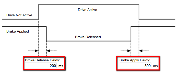
The drive will stay enabled after the brake is engaged for the time of MOTOR.TBRAKEAPP. This allows enough time for the holding brake to lose power and engage, before the drive disables.
The parameter MOTOR.TBRAKERLS is the time delay between the drive enabling and when motion commands can be accepted. When the drive is enabled by turning on the Controlled Stop input, the drive will enable and the brake will release within about 10ms. Then the drive will wait for the time of MOTOR.TBRAKERLS before any motion commands will be accepted.
Sequence:
- Controlled Stop input goes low (open circuit)
- Motor decelerates at CS.DEC
- Speed drops below CS.VTHRESH
- CS.TO timer starts counting down (speed must remain below threshold)
- CS.TO timer completes
- Brake engages
- MOTOR.TBRAKEAPP timer counts down
- Drive disables
Sequence:
- Controlled Stop input goes high (closed circuit)
- Drive enables
- Brake disengages
- MOTOR.TBRAKERLS timer counts down
- Motion can be commanded
Controlled Stop then Dynamic Brake:
The disable mode can also be configured to #4 (Controlled Stop then Dynamic Brake). The drive will decelerate the motor using the commanded deceleration rate of CS.DEC. After the velocity reaches CS.VTHRESH and the CS.TO counter completes, the drive will switch into dynamic braking to bring the motor to a complete stop.
Hardware Enable and STO
When the hardware enable or STO is turned off, the motor will coast (freewheel). Deceleration depends entirely on external forces. The motor has no power and the output power stage of the drive is completely switched off. There is no controlled stop or dynamic braking. If there is a vertical load or other external force applied, then the motor will be driven by the external force immediately after the drive disables. The holding brake will not engage in time to prevent motion and will probably not be able to stop the motor while it is moving. This can damage the holding brake.
Software Enable
The “Disable” button in Workbench will execute a disable based on the disable mode selected in the Enable/Disable screen (DRV.DISMODE). Using the software enable to disable the drive via a fieldbus will have the same effect as the Disable button in Workbench. If the disable mode is set to one of the Controlled Stop modes, then the software enable will behave the same as the Controlled Stop input.
Fault Conditions
A software disable condition due to a fault condition can have different behaviors. Some faults will cause the motor to disable immediately, while others will activate dynamic braking. The only difference in the case of a fault condition is that the controlled stop deceleration rate is not used. The motor will coast. A vertical load will fall, if the motor is moving faster than the controlled stop velocity threshold. To prevent a vertical load from falling, set MOTOR.BRAKEIMM = 1. This will cause the brake to engage immediately, regardless of the speed, whenever the drive disables in a condition that doesn't control the deceleration. The disable could be from the hardware enable, the STO, any software disable command, or any fault condition.
Note: Setting MOTOR.BRAKEIMM = 1 will not cause the brake to engage immediately during a normal Controlled Stop condition. The motor will be allowed to decelerate to the velocity threshold before the brake is engaged. But it will engage the brake immediately during any disable condition that does not control the deceleration, such as STO, hardware disable, fault condition.
Damaging a Holding Brake
With MOTOR.BRAKEIMM = 1, there is concern about damaging the brake by engaging the brake while the motor is still moving. This is necessary for vertical loads in the event of a fault condition to keep the load from falling. But it will damage the holding brake. Depending on the load inertia and speed, the brake may or may not be able to stop the load if it is already moving. The brake is designed to hold a load, not to stop a moving load. If the brake is engaged while the motor is moving, the friction surfaces will start to glaze over and lose some of the holding torque. This damage is permanent.
Manual Control
The brake can be manually engaged and disengaged by using the parameter MOTOR.BRAKERLS. A value of zero allows the drive to control the brake. Setting it to 1 releases the brake, and setting it to 2 engages the brake. Also, a digital input can be configured for Brake Release. When the input is activated, the brake will release while the drive is disabled.
Back to top
Comments
My application is a grinding machine. Drive is controlled by analog input and HW Enable.
Those are the only connection to the drive.
I want the grinding wheel to stop fast with dynamic braking when HW Enable goes low.
How to do this?