


 Home >
 Knowledge Base >
 Community >
 Downloads >
Configuring The AKD X9 EEO AS General Digital I/O
Overview
The X9 Port on the AKD drive is generally used as an encoder input, EEO (encoder emulated output), or not used. However, the AKD also has the feature to use the X9 port as general I/O.
Wiring the AKD X9 General I/O
The following document provides examples that illustrates how to wire the AKD Gen 1 X9 connector’s I/O for General use. Note from the AKD Installation Manual the following chart which indicates 3 programmable I/O channels are available ( channels 9, 10, and 11 ).
X9 I/O Wiring Connectivity

When X9 is uses for general I/O per the pin outs above, they are single ended I/O are referenced to pin 3 “I/O-GND" on connector X9

Note: The differential connection will provide much better noise immunity than the single Ended connection . Although the manual shows a 150 ohm terminating resistor internally, it is actually required externally and customer supplied at the AKD Drive’s X9 I/O connections.


ACTIVE HIGH ONLY! Minimum allowable load impedance is 100 ohms

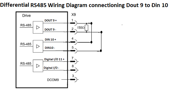
The differential connection will provide better noise immunity than the single ended connection.

The DOUT9 and the DIN10 are both referenced to the same I/O-GND.
X9 I/O Configuration Parameters:
DRV.EMUEMODE = 10: Allows the X9 connector to be used as a General Purpose I/O
DIO9.DIR, DIO10.DIR and DIO11.DIR: This parameter changes the direction of the general purpose IO from the X9 connector. If DIOx.DIR is set 0 then the IO configured as an input, while if DIOx.DIR is 1 the IO is configured as an output.
DIO9.DIR controls Pin 1
DIO10.DIR controls Pin 4
DIO11.DIR controls Pin 7 .
This parameter can be set at any time. It will be ignored unless DRV.EMUEMODE is set to 10
DOUT9.MODE, DOUT10.MODE and DOUT11MODe: Sets the functionality of the digital output(s). The table below summarizes the digital output modes; for detailed descriptions of each mode, see Digital Inputs and Outputs. This parameter only has an effect when DRV.EMUEMODE is set to 10 (General Purpose I/O).

Mode 0-User (Default = 0): The output state is decided by the user or fieldbus. This mode is valid for all opmodes and command source combinations.
Mode 23 – Compare Output: This output mode reflects the state of the compare output. There are two compare engines and DOUTx.PARAM selects the engine (0 or 1) that controls this output
Mode 26 – PWM Output: This output mode outputs a Pulse Width Modulation (PWM) signal. Only available on digital outputs 9, 10, and 11. See PWM Output.
DOUT9.STATEU, DOUT10.STATEU and DOUTT11.STATEU: Sets the state of the digital output node as follows:
0 = deactivated
1 = activated
DOUT9.STATE, DOUT10.STATE and DOUTT11.STATE: Reads the state of one digital output according to the value stated in the command.
0 = Off
1 = On
DIN9.STATE, DIN10.STATE and DIN11.STATE: This parameter allows the user to see the actual level of the input signal, when the IO is set to input mode. Parameter value is 0 if signal is low and 1 if signal is high. DIOx.INV can affect the value in this register.
This parameter can be read at any time. The value is only guaranteed to correspond to the output on the X9 connector when DRV.EMUEMODE is set to 10 and the DIOX.DIR is 0.