


 Home >
 Knowledge Base >
 Community >
 Downloads >
Driving STO Inputs from Relays
Implementation of STO Inputs
There are two types of STO input in common use today:
- DC-DC Type: isolated STO input based on using a DC-DC converter to power the date driver circuitry.
- O-C Type: opto-isolated input of a drive that acts upon the gate driver circuit.
Here is a simplified drawing of an O-C Type input:

In practice, some extra circuit is included to enforce a 5V minimum threshold and to suppress incoming test pulses. From the user’s perspective, it’s similar to ordinary, isolated, digital inputs and only a low current such as 15mA is required. In this example, the photo-transistor is in series with the power supply for the gate driver.
The drawback with a O-C Type STO input is that if the photo-transistor fails short-circuited then the STO has been defeated. For this reason, and to reach a low PFHD, O-C Type STO inputs are generally found in drives implemented as part of a pair of inputs with the diagnosis.
Here is a simplified drawing of a DC-DC Type STO input:
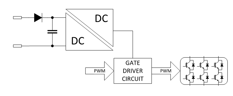
The DC-DC converter doesn’t just act upon the gate driver circuit; rather it powers the gate driver circuit. The construction of the DC-DC converter allows for a fault exclusion to be made against the failure of its transformer. When the DC-DC converter fails in some other manner, that failure always results in no power being transferred; namely, it has a safe failure fraction of 100%. DC-DC Type STO inputs are widely used in servo drives as they can achieve a low PFHD using a single channel. For architectural reasons, it is only possible to reach SIL2 or Pl/d using a single channel.
It can be observed, from the simplified sketch, that DC-DC Type STO inputs present a mainly capacitative load to the customer’s driving circuit. The steady-state current drawn is typically on the order of 50mA, however, the current at turn-on is limited by the impedance of the driver and some impedance from the wiring.
STO Inputs in Kollmorgen Drives
All Kollmorgen drives with a single STO input use a DC-DC Type input. This also applies to the AKD-C/AKD-N family – albeit with a distributed DC-DC converter.
In a drive with two STO inputs, it is possible to have two similar STO inputs or to have one of each STO type and thereby reach SIL3 and PL/e.
The STO inputs of a complete set of current Kollmorgen products are summarized below:
| STO1 | STO2 | |||
|---|---|---|---|---|
| Drive | Style | Effective Input Capacitance | Style | Effective Input Capacitance |
| AKD-x003...024 | DC-DC Type | 1.0µF | – | – |
| AKD-x00306, AKD-x00606, AKD-X01206 Rev F only | DC-DC Type | 10 Ohms series to 1.0µF | – | – |
| AKD-x048 | DC-DC Type | 3.3µF | DC-DC Type | 3.3µF |
| AKD-N, local STO | DC-DC Type | 10.0µF | – | – |
| AKD-C | DC-DC Type | 30.0µF | – | – |
| S700 | DC-DC Type | 10.0µF | O-C Type | – |
| AKD2G Safety Option 1 | O-C Type | – | O-C Type | – |
For more information on STO wiring, please see the AKD Installation Manual.
Outputs of Safety Relays and Safety PLCs
There are various styles but here we are interested in two:
- High-side drivers.
- Force-guided relays.
High-side drivers feature current limiting and diagnosis. They may emit test pulses. They can detect when the output is shorted to 24V. Output current capabilities vary from manufacturer to manufacturer and channel. Almost all support 50mA loads and some support as much as 2A. Their current limiting allows them to be connected to capacitative loads such as DC-DC Type STO inputs without any lifetime limitation.
Force-guided relays are also used. These devices are constructed so that the monitoring contacts match the state of the load contacts. Force-guided relays have the same type of switching characteristic as ordinary relays; i.e. X amps at Y volts DC into a resistive load for Z cycles. As an example consider part number SIS 112 24VDC from Elesta; this part is used in the KSM. The contact life is a function of the current:
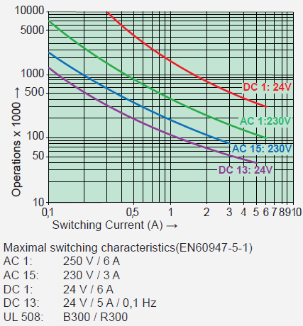
Note: The graph and specifications provided are from ELESTA GmbH.
The STO input shouldn’t be operated at 10Hz so the DC1 curve (red) is of the greatest interest. At 2A more than 700,000 cycles should be achievable.
It must be noted to achieve this high life expectancy assumes switching a resistive load.
Inductive loads reduce life because of the high voltage applied to the contact at turn-off; this can generally be alleviated by shunting the load with a freewheeling diode.
Capacitative loads reduce life because of the high current flowing through the contact at turn-on; this can generally be remedied by limiting the current with a resistor or possibly with an active current-limiting circuit. The manufacturer doesn’t give a number of cycles vs. a specified capacitance but there is some evidence to expect 10,000 cycles with a 1.0µF load.
Let’s consider what 700,000 cycles mean. Assume eight-hour working.
| Mission Time | ||
| Years | Minutes | Period of STO Activation (minutes) |
| 20 | 3504000 | 5.01 |
| 10 | 1752000 | 2.5 |
If STO is activated less often than every 5 minutes, then the relay will last 20 years. Using a relay is a practical means of switching STO inputs, provided that measures are taken to achieve the full life of the relay.
Let’s consider what 10,000 cycles mean. Assume eight-hour working.
| Mission Time | ||
| Years | Minutes | Period of STO Activation (minutes) |
| 20 | 58400 | 5.84 |
| 10 | 29200 | 2.92 |
If STO is activated less often than every 5 hours, then the relay may last 20 years.
Note: Kollmorgen does not recommend switching capacitative loads directly using a relay and this includes DC-DC Type STO inputs. However, there are applications where the STO activation is sufficiently infrequent that the user may not encounter a problem.
Driving “O-C Type” STO Inputs Using a Relay
These inputs have little or no input capacitance and can be driven with a relay. There will be some stray capacitance associated with the wiring itself but this is not normally a problem if in doubt measure it with an oscilloscope.
Driving “DC-DC Type” STO Inputs Using a Relay
If possible use a Safety Relay/ Safety PLC that has a solid-state, current-linting output but if this is not possible then Kollmorgen recommends inserting a 12Ω in series with the relay contact to limit the in-rush current to 2A when using a 24V supply. The rating of the resistor depends upon the number of loads and their current draw. Up to four drives can be driven in this manner:

Example: Four drives from the AKD-x003...024 family, these have “DC-DC Type” STO inputs and draw 45mA each.
- Resistance=12Ω
- Power=4*(45mA *45mA *12Ω)=97mw (resistor must be at least 97mW/66% - use 0.5W or larger to reduce the surface temperature)
- Voltage drop=45mA*12Ω*4=2.16V which is 9% of the supply rail
For example: If driving eight drives, then use two resistors and connect four drives to each resistor but note that the in-rush current is now limited to 4A and the relay life will be consequently reduced.
This example excludes the STO inputs of AKD-C and AKD-N, these inputs are DC-DC Type but are of different construction having larger input capacitance and different input currents.
It is convenient to mount the resistor within a DIN rail terminal. Here are two possible parts:
- Weidműller: WDK 2.5/D/3
- Weidműller: WDK 2.5/D
Impact on Safety Certification
It is mandatory to consult the notified body when modifying a certified safety installation.
However, adding a resistor is not expected to raise significant objections. The resistor can be selected so that short-circuit may be excluded (refer to Table D.14 of ISO_13849-2_2012). It is then necessary to consider the effects of change of the resistor value, for example:
| Fault | Effect | Possible Mitigations |
|---|---|---|
| Resistance reduced by 50% | Reduction in the life of the relay contact |
Periodic testing of the safety system. Consider the periodic measurement of the resistance. |
| Resistance increased by 100% | Increase in resistor dissipation. | Adequate sizing |
| Reduction in voltage supplied to STO input. | This has either no effect or is safe because it causes STO |