


 Home >
 Knowledge Base >
 Community >
 Downloads >
Encoder Installation Instruction for IDC Stepper Motor 802-004
Following are the instructions for adding the Encoder 802-004, which is the 0.25" SHAFT, 500 LINE ENCODER for stepper motors. Attached is the original PDF.
NOTE: S3 & S4 motors require cover mod. for cable
General Information
The LDA encoder is designed for installation directly on the motor shaft. It provides a factory pre-assembled feature that eliminates the need for any adjustment of disc gap, disc alignment, symmetry and phasing while installing it on the motor shaft.
Special Care for Installation
The encoder must be handled with care to avoid exposure to dust, dirt and grease, resulting in malfunction.
Extreme care is required for removing “MEMORY PLATE”, since the encoder is preadjusted and pre-set with “MEMORY PLATE”.
Necessary steps shown in assembly procedure must be taken before removing “MEMORY PLATE:”.
Motor Mounting Requirements
| Shaft Tolerance | Squarewave | 1/4” | 3/8” | +0 | -.0006” |
|---|---|---|---|---|---|
| 1/2” | +0 | -.0007” | |||
| 8mm | 10mm | +0 | -.015mm | ||
| Sinewave | 1/4” | 3/8” | +0 | -.0003” | |
| 1/2” | +0 | -.0004” | |||
| 8mm | 10mm | +0 | -.009mm | ||
| Shaft Length | .70” / .90” | ||||
| Mount Holes | #4-40 x .25” deep 2 holes 180° apart on 1.811” dia., ±.004” B.C. | ||||
| Shaft Runout | .004” TIR Max | ||||
| Perpendicularity | .0012” TIR Max (Shaft to Mounting Surface) | ||||
| Shaft End Play | 1- 200 PPR | .0216” (Max.) | |||
| 201- 300 PPR | .0177” | ||||
| 301- 400 PPR | .0137” | ||||
| 401- 600 PPR | .0078” | ||||
| 601- 800 PPR | .0059” | ||||
| 801- 900 PPR | .0043” | ||||
| 901-1200 PPR | .0039” | ||||
| 1201-1600 PPR | .0020” | ||||
| 1601-1800 PPR | .0015” | ||||
| [each direction] | |||||
Assembly Procedure
| 1. |  |
Apply tie-lock to two hex socket set screws placed on the side of hub. Be sure that the two set screws are loosened. |
| 2. |  |
Place the encoder body over teh shaft by holding the plastic ring underneath the “MEMORY P L AT E ” , and press it into the mounting surface. Do not use force when you have difficulty in insertion. Forcing the insertion destroys all pre-adjustments precisely made by the factory. Check to see if the two set screws are loosened enough. |
| 3. |  |
Apply tie-lock to the tip of #4-40 x 1 pan head screws provided, and fasten the encoder body to the mounting surface. FASTEN SCREWS ALTERNATELY. TIGHTEN WITH 5.2 in/lb Cover screw heads with 600-001 varnish. |
| 4. |  |
Alternately fasten the two set screws provided on the side of the hub with 1.5 mm hex key wrench to the motor shaft. TIGHTEN WITH 5.2 in/lb Be careful not to cut or pinch electrical circuits and not to put greaase or dirt on circuit board while tightening screws. |
| 5. |  |
Loosen the two philips screws above the plastic ring first, then remove the outside of the two philips screws. |
| 6. |  |
Remove the “MEMORY PLATE” with the plastic ring. [Save the “MEMORY PLATE” for future removal and reinstallation of the encoder.] |
| 7. | 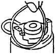 |
Place O-ring in the groove of the encoder flange. |
| 8. |  |
Apply silicon grease to the inside of the cover around the cut-end. Place the cover so that the open-cut is placed over the lead cables. |
| 9. |  |
Attach the cover with the two flat head machine screws provided. Tie-lock is to be applied. TIGHTEN WITH3.5 in/lb |
Removal Procedure
- Rotate the hub so that the two set screws will position to loosen and tighten from the encoder side . Please not that you cannot loosen and tighten the two set screws from the encoder side if stop position of the hub is off 180°.
- Align the two threaded holes of the hub with the two threaded holes of the housing.
- Place the “MEMORY PLATE” over the housing and the hub.
- Fasten the “MEMORY PLATE” with the four screws provided until the ring is snugly placed over the hub end.
- Loosen the two set screws located on the side of the hub.
You are now ready to remove the encoder.
It is not recommended that the encoder be removed and reinstalled unless absolutely necessary. The frequent removal and reinstallation may affect the electrical alignment.